top of page
Crosswalk and Traffic Light Detection
Here is described how crosswalks and traffic lights are detected via Integral framework technology.

Integral Framework
Proposed algorithms for detecting crosswalks and traffic lights are designed to run in real time with small computational complexity. Since objective of the proposed algorithms is to be installed on AVS where missing targets is more critical than misdetecting targets, more weight was putted on reducing false negative errors rather than on reducing false positive errors. In addition, when these two algorithms are combined by integral framework, a problem which is frequent false positive errors

by the individual algorithms can be solved. Entire sequences are described in Fig. 2 A. Crosswalk Detection For detecting crosswalks, V values of HSV domain image was used. After converting an original image to a V image, 1-D mean filters which are perpendicular to x-axis in image coordinate was applied. Length of filters should be larger than length of intervals between white lines of a crosswalk. Since the intervals become wider as a crosswalk comes closer to a camera, length of filters would be proportional to y-coordinate. The filtered result is shown in Fig. 3b. Using the filtered result image, two binary images shown as Fig. 3c should be evaluated. The binary images are gained by thresholding differences between the original V image and the filtered result image. For one of binary images, each pixel is assigned by 1 when its difference is larger than θ. For another one, each pixel becomes 1 when its difference is smaller than −θ. Those binary images will be denoised through erosion, dilation and blob-labeling. A reason why absolute values of differences weren’t used is that it is possible to denoise efficiently when binary images are divided. If one binary image with absolute value of difference have been used, many noises would be hard to be eliminated because they can be combined and become too large to be distinguished as noises. After the de-noising sequence, the two binary images are

combined by OR operation. If there is crosswalk on a road, a band-like binary object like Fig. 3e would be shown. The band-like object can be searched by 2-D mean filter. Width of these filters are equal to width of road. Since height of crosswalk is larger when crosswalk comes closer to camera, height of these filters are proportional to y-coordinate. When result of the filter is over a predifined threshold, a presence and location of crosswalk can be obtained. A final result is shown in Fig. 3f. B. Detecting a Traffic Light A proposed algorithm for detecting traffic lights is mostly referred to a algorithm using probabilistic template matching [1]. However, since the refered algorithm was just for checking states of traffic lights, it knew a size and position of detected traffic light. That means the referred algorithm is too slow to detect traffic lights for whole image and its computational complexity is increased linearly with the number of templates for traffic lights. To solve these problems, the referred algorithm was improved for detecting traffic lights. At first, an original was converted image to HSV domain image, becuase HSV domain is robust to changes of brightness. Secondly, U which shows the probability that each pixel is the center of traffic light was evaluated. U is calculated using saturation and brightness value of HSV domain image. An equation for U is written as [1].

Next, G(H, S, V) which is a probability that templates centered at each pixel looks like a traffic light was evaluated. G(H, S, V) is calculated by U and the number of pixels satisfying a predefined range of H and S. It is unnecessary to evaluate many G(H, S, V) image, because a large template contains all templates which is smaller than that. Therefore it isn’t needed to be evaluated for other templates when the one for the largest template is known. In the referred
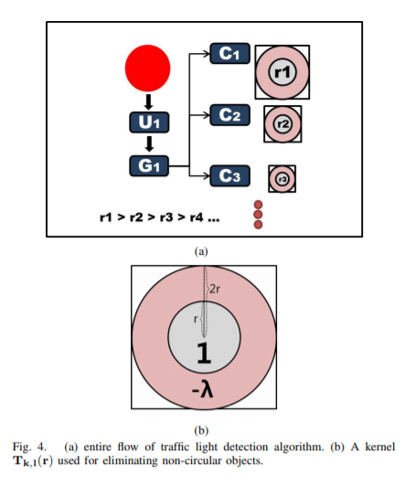
algorithm, G(H, S, V) also described a rectangular black area of traffic light, but it was removed to reduce its computational complexity. When it has a term describing the black area, many G(H, S, V) images should be evaluated for every size of templates. G(H, S, V) can be described as

θS is a predefined threshold for saturation value. In addition, Tk,l(r) is a Gaussian-filtered template which has a centered circle. This can be described as

where G(σ) is a gaussian filter with variance σ. Traffic lights can be detected by convoluting G Image with a circle-like kernel Tk,l(r), becuase the evaluated G(H, S, V) can include non-circular shape objects. The kernel can be represented as Fig. 4b, and

where λ is a predefined constant. A result image is obtained R(r) by convoluting G image with Ck,l(r). Since various sizes of traffic light templates should be applied, the kernels Tk,l(r) and resulted values of each pixel are various. As a result, each pixel has as many values as the number of template sizes. Using the result image R(r), traffic lights can be detected when maximum result value is over a predefined threshold θR. Ri,j(r) means a resulted value of pixel (i,j) with a radius of traffic light template, r. It can be described as

C. Integral Framework Even though false positive errors are occured frequently by the proposed individual algorithm, each algorithm shows a small false negative error ratio. When results of the two algorithms are combined by integral framework, false positive error ratio will be lower than that of the individual algorithm. As a result, the integral framework has generality which is not to miss targets and accuracy that makes false positive error ratio lower. This framework uses an assumption that traffic lights are located next to crosswalks.
IV. RESULT The proposed algorithms were tested with movies captured by cameras on a vehicle. Three cameras were mounted on the vehicle. First one is a zoom camera for distant view, second one is a front camera for nearby front view and last one is a tilted camera for looking down a road closely. Results are shown as Fig. 5. Fig. 5a shows an image captured by the tilted camera, Fig. 5c is captured from the front camera and Fig. 5d is from the zoom camera.

Table. I shows result of the two algorithms and the integral framework. The traffic light detection algorithm was tested by the zoom camera and the front camera, and the crosswalk detection algorithm was executed by the tilted camera. Ground truth are images in which there are crosswalk or traffic light and they were picked out by hand. TP means the number of true positive result and FP is the number of false positive errors. As shown in Table. I, true positive ratio is over 95 percent and false negative ratio is under 5 percent. Most false negative errors were resulted from size of the objectscrosswalk and traffic light-which is smaller than minumum size.(e.g. 5 pixels with height of crosswalk and with radius of traffic light) Note that, more false positive and false negative errors were emerged, when each algorithm was applied respectively. The number of false positive error is reduced to 4 via the proposed integral framework. The proposed crosswalk and traffic light detection algorithm were performed on one 2.4GHz CPU core and 2GB memory, and the computational time was less than 17ms for crosswalk detection algorithm and 25ms for traffic light detection algorithm respectively.

bottom of page